
Valve Movement Notes
Ron Royle (Member 687) – 10th April 2025
Firstly, our apologies to Ron for the delay in publishing his technical article. Combined illness (and a degree of brain fade!) with two committee members meant this item got overlooked!
Over to Ron...
At our last zoom meeting the subject of cam and valve operation was discussed, something that has intrigued me, given the rather lively performance of our S800's. Some time ago, I made the effort to plot the valve movement of the standard set up, given that I could not find any information regarding valve movement,and I thought it could be of interest to examinewhat was actually going on.
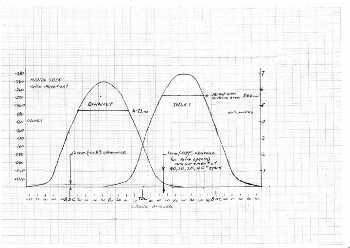
So, given that I have a spare fully assembled head with standard cams I set to and measured the movement of both the inlet and exhaust cams. I set up a dial gauge with a large flat follower to the cams so as to measure the movement of the bucket and valve, including the initial clearanceof the various components. To measure the angles a large diameter protractor was fitted to the camshafts for accurate angle measurement.
The initial position of the protractor was set with an overlap of 40 degrees between the valves when the total valve clearance was 1 mm or 40 thou, as stated in the S800 Shop Manual, page 5. Previous reading indicated that European practice is that offsets are measured from 1mm (39 thou) clearance and thatAmerican practice seems to be 5o thou, as apparently it is accepted that there is no gas flow until this approximate opening is reached.
I did the measured set-up with no initial clearance, as I wanted to track the cam movement during the period of initial clearance take up, as well as the actual valve movement.
A further factor to be take into consideration with valve timing, is the relationship between the length of the con rod compared to the length of the stroke. In the case of the Honda the relationship is quite low compared to most engines, at 1.75. This causes the piston to accelerate downwards much faster initially than it decelerates to the end of the stroke, resulting in the maximum velocity of the piston being toward the top of the cylinder,in fact at 74 degrees,by calculation, from the top, not 90 degrees, as might be expected.
Therefore any conclusions drawn must be regarded as a first approximation only, a final result can only be ascertained by experiment and actual operation, which Honda undoubtably did.
Results.
1. There is an initial slow opening and closing of both cams, during the valve clearance from zero to 0.2 mms or 8 thou. This idea of initial slow opening and closing seems to have been introduced by Harry Ricardo, way back, his reasoning being that it would quieten the valve operation. You would think hardly a factor in engines designed for tanks, lorries and aeroplanes of the period. A more likely reason for its inclusion now, would be to lessen the impact of the various components on each other during clearance take up. This slope of this initial take up is, in fact, about ¼ the rate of the full opening rate. This can be seen in the diagrams.
2. The standard openings quoted at 1 mm lift are accurate at 20, 40, 40, 20 degrees.
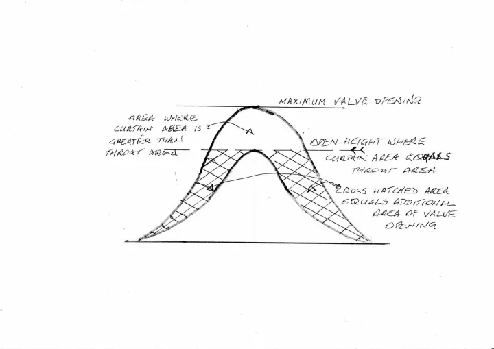
3. Maximum valve opening heights seem to be often quoted, but rarely is the height quoted when curtain area equals throat area. For the standard Honda valve and throat, the figures are;
Inlet valve Exhaust valve
Maximum valve opening 7 mm 6.5 mm
Opening when
curtain area = throat area 5.6 mm 4.7 mm
In other words, if the valve opens further than these dimensions, (5.6 and 4.7 mm,) the gas flow will be controlled by the fixed throat area and not the increasing curtain area. However, significant advantage is gained by this further opening of the valve past the throat limiting point. A little difficult to explain, but hopefully this is shown in the attached roughdetail sketch of the valve movement.
Note regarding regrinding of standard cams.
In discussion at the last meeting, consideration was given to increasing the total valve opening, and we concluded that this can only be done by reducing the base circle diameter.
I have checked with a local cam grinding guy, speedway engines, who informs me that it is common for them to increase the maximum diameter, that is cam height, by adding weld to the cam peak, and then form grinding.
A suitable special rod is used, however, given that these are competition engines he could not vouch for the longevity of the cam peak.They possibly only survive as long as the mains and big ends, but possibly a solution worth exploring for competition purposes.